Components evaluated in the Draft SEIS/EIR
Train Box Extension
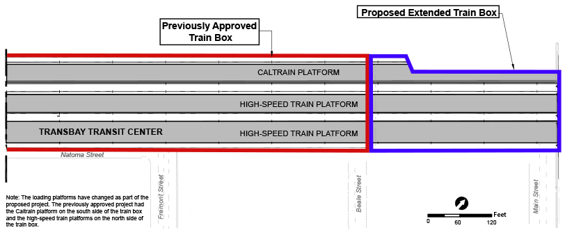
The 2004 FEIS/EIR-approved train box design has the eastern end of the underground train box terminating at Beale Street. The proposed Train Box Extension would extend the train box east one block to Main Street. The proposed extension is compatible with platform design specifications from the California High-Speed Rail Authority and creates the opportunity for a more direct route for the planned pedestrian connection to the Embarcadero BART/Muni Metro station on Market Street.
Intercity Bus Facility
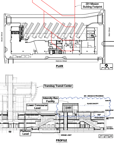
The 2004 FEIS/EIR included an intercity bus component as part of the Transit Center building. The proposed Intercity Bus Facility would take advantage of the area above the extended train box to construct a new facility between Beale and Main Streets, east of and across Beale Street from the Transit Center. It would serve Amtrak and private bus operators such as Greyhound.
Ventilation and Emergency Egress Structures
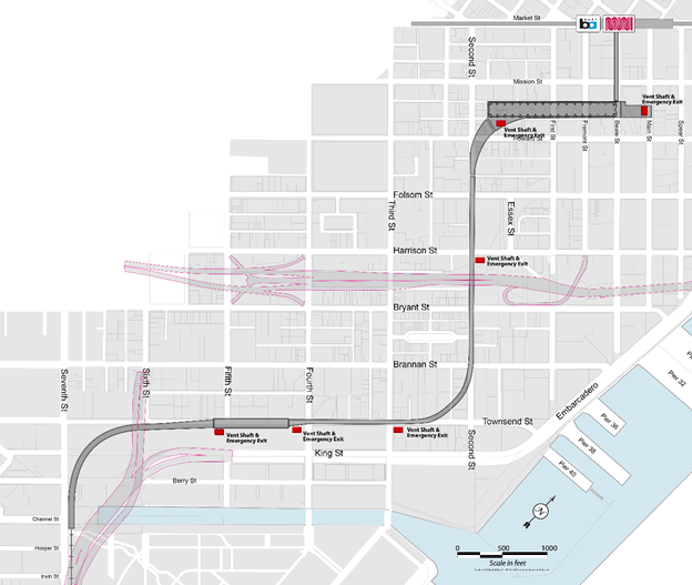
The 2004 FEIS/EIR-approved design discusses the need for vent structures along the DTX alignment. The proposed ventilation structures would be co-located with emergency tunnel exits. Their locations have been refined as follows:
- Fourth and Townsend Street Station, one at each end
- 701 Third Street at Townsend Street or across the street at 699 Third Street and 180 Townsend Street
- Second and Harrison Streets (southeast corner)
- Transit Center, one at each end
The height of the ventilation structures would vary depending on adjacent development. Two exhaust fans would be located at the west end of the Transit Center. Design and siting of the ventilation structures will follow National Fire Protection Association Standard 130.
Portions of the ventilation and emergency egress structure sites at Third/Townsend Streets, Second/Harrison Streets, and the east end of the Transit Center may be available for future development, if approved by the City.
Taxi Staging Area
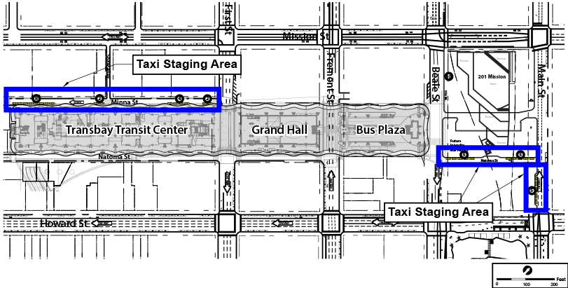
The 2004 FEIS/EIR includes taxi service. Specific curbside passenger loading and unloading space for taxis is proposed along the south side of Minna Street between First and Second Streets, along the north side of a proposed new section of Natoma Street between Beale and Main Streets, and along the west side of Main Street between Natoma and Howard Streets. The proposed Taxi Staging Areas would be a convenience for passengers coming to or leaving the Transit Center.
BART/Muni Underground Pedestrian Connector
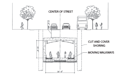
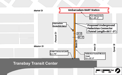
The 2004 FEIS/EIR-approved design included a pedestrian tunnel under Fremont Street between the Transit Center and a BART/Muni Metro station on Market Street. The proposed BART/Muni Underground Pedestrian Connector is an 800-foot pedestrian connection underneath Beale Street linking the Embarcadero BART/Muni Metro Station with the Transit Center. The new design takes advantage of the extended train box to provide this direct connection.
Bicycle/Controlled Vehicle Ramp
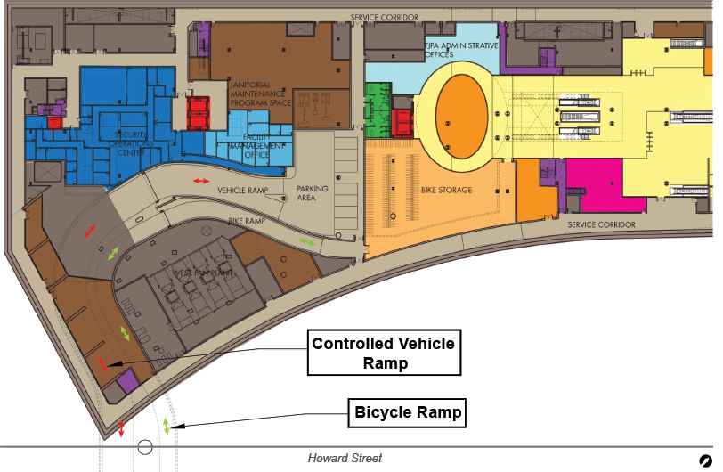
A bicycle ramp would provide access from Howard Street to below-grade bicycle facilities within the Transit Center. A separate controlled-access vehicle ramp to the Lower Concourse (for use by emergency and approved maintenance vehicles) would run parallel to the bicycle ramp. The Bicycle/Controlled Vehicle Ramp would reduce conflicts for pedestrians, bicyclists, and motorists and improve access to the Phase 2 bicycle storage area.
Widened Throat Structure
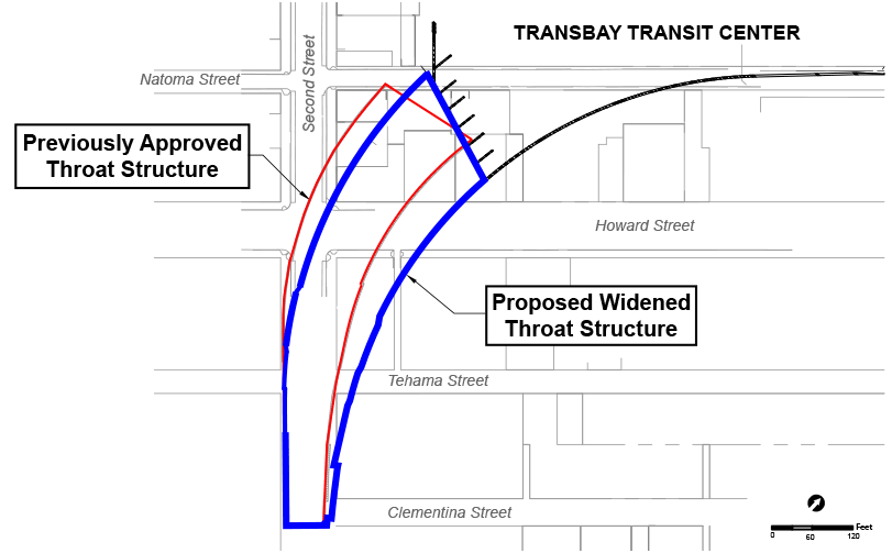
The 2004 FEIS/EIR-approved design for the DTX includes a connection between the underground tracks in Second Street and the train box below the Transit Center (referred to as the “throat structure”). Existing development constrains where the throat structure alignment must widen from the three-track tunnel in Second Street to six tracks entering the west end of the Transit Center, and the width of the alignment depends on the curvature of the tracks. The previously approved design has a curvature radius of less than 545 feet. The proposed Widened Throat Structure calls for a 650-foot radius curve, which has been approved by the California High-Speed Rail Authority.
Rock Dowels
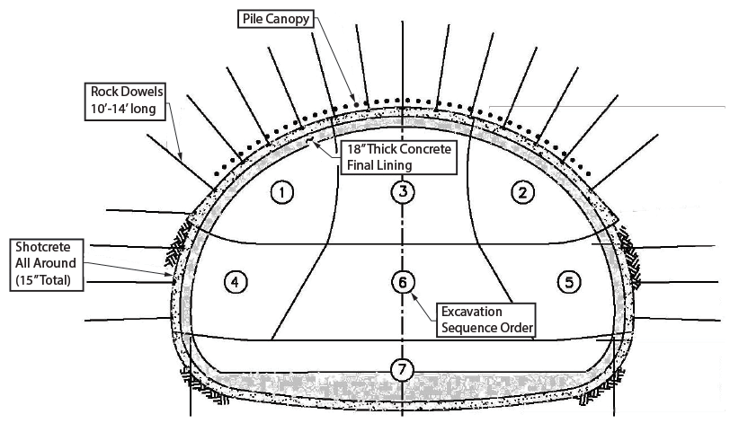
Rock dowels are approximately 15-foot-long rods that would be installed along the mined tunnel segment. Installation of the rock dowels would improve safety during construction of the tunnel.
Parking at AC Transit Bus Storage Facility
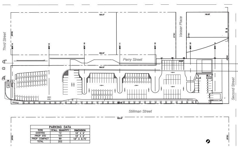
The 2004 FEIS/EIR-approved design includes a bus storage area for AC Transit’s exclusive use. The proposed AC Transit Bus Storage Facility Parking would expand the use of this facility to allow for off-hours/nighttime or special event parking when the facility is not being used by AC Transit, to help offset the projected shortfall of public parking in the area. The AC Transit bus storage facility would have two potential modes for off-hours parking: 202 valet-parked spaces or 167 self-parked spaces.
Fourth and Townsend Underground Station Realignment
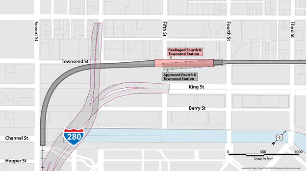
The 2004 FEIS/EIR-approved design includes an underground Fourth and Townsend Street Station located partially under the Caltrain railyard. The proposed Realigned Fourth and Townsend Underground Station would be realigned to parallel Townsend Street and shift the station into the public right-of-way, which would improve operations and support City and County of San Francisco’s planning efforts.
Tunnel Stub Box
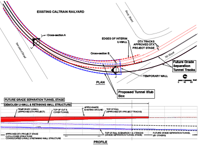
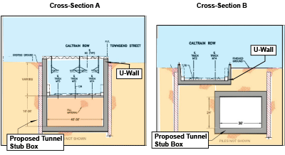
The 2004 FEIS/EIR-approved design includes a retained-cut structure, or U-wall, at the west end of the Caltrain railyard for trains to transition between the underground Fourth and Townsend Street Station and the at-grade alignment to the south. The proposed Tunnel Stub Box is a new below-grade train box stub, which would be built beneath the U-wall to accommodate future grade separations and expedite future arrival of below-grade Caltrain and high-speed trains.
Additional Trackwork
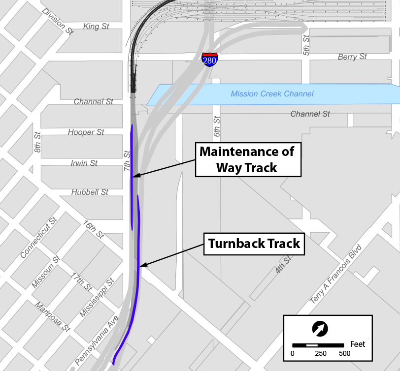
The proposed Additional Trackwork comprises a turnback track and maintenance-of-way storage track to be constructed within the existing Caltrain right-of-way between Hooper Street and Mariposa Street, immediately east of Seventh Street.
